
Formwork
Column Formwork
Conventional
formwork was used to column formwork. It was fixed to 200 mm height kicker for
maintain average pouring height of 1800 mm during the concreting of each
element. The formwork box was made with 15 mm thick coated plywood and 50 mm ×
50 mm wooden battens. 6 mm sponge sheet layer was kept around the perimeter of
the column kicker to stop the grout leakages. Then GI pipes were fixed to the
formwork with form ties from four sides of the column.
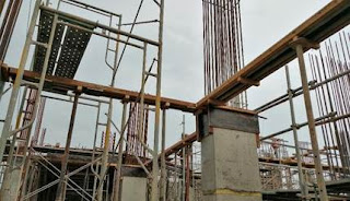
Formwork
was kept steady and vertically using Acro jacks, GI pipes, T jacks, U jacks and
necessary props. If jacks were not suitable for the location of the column,
High Tension Cables and 300 mm Turn Buckles were used. (Figure 1.1).
Form
oil was applied all formwork inner surfaces, so that it will avoid concrete
sticking with planks and will be easy to de-shutter.

Verticality Check of the Column
Formwork
When marking the location of the column, we marked
another line, which is 200mm off to column marking. 200 mm offsets were drawn
at four sides of the column to check the horizontal distance between the outer
formwork surface and the plumb line. After finishing the column formwork, a
wooden strap was fixed on top of the column box with an extended edge of 200mm
from a side. Then a plumb bob was freely suspended at the edge of the strap.
(Figure 1.2).

Figure
1.2. Verticality Check
![]() Horizontal
distance between
= offset – plywood thickness
Horizontal
distance between
= offset – plywood thickness
Outer formwork surface and plumb
line (x) = 200 mm – 15 mm = 185
mm
Top, bottom and middle readings should be equal in
order the column to be exactly vertical. If a deviation in the readings occurs,
the adjustable props were used to correct the error. The allowable error
tolerance was ± 5 mm up to 1.5 m height and ± 10 mm up to 1.5 m to 15 m
height.
Like that two
numbers of vertical faces are checked for vertical alignment; in each faces two
numbers of center plum bobs were fixed.
Slab Formwork
In slab formwork, before placing beam bottoms we have
to mark the +1000 mm level from floor in columns. Then using general
arrangements of the slab, the levels and heights were identified. According to
those levels, column kickers were placed. (Figure1.3).
Figure 1.3. Column kicker
Figure 1.4. Beam bottom
Column head level = Floor to floor
height – Beam height – Plywood thickness – 1000mm
After that, beam bottoms were placed on 50mm × 50mm
timber of kickers and bottoms were aligned to correct locations using plumb bob
and offset lines. (Figure 1.5). Then, beam bottoms were levelled using nylon
rope and bottom heights were adjusted using acro jacks, T jacks, U jacks.
Figure
1.5. Beam Bottoms Placing
Beam side board height was calculated using beam
heights and slab thickness. Depending up on the beam height, number of P cones
for horizontal plane can be decided. One P cone row for beam height up to 750
mm and above 750 mm height beams more than one rows used. Horizontal distance
between P cones should be around 900mm for beam height up to 750mm beams and
around 600mm for beam height is more than 750mm beams. All beam side boards
were brazed using GI pipes and form ties to get proper strength of formwork as
well as to maintain the alignment.
For slab panel, 50mm GI pipes were laid around 250mm
center to center measurement on the 100mm × 100mm timber planks which was laid
on U jacks with scaffoldings. Also 50mm × 50mm timber lining was done with
parallel to GI pipes for 15mm plywood board joining.
Nailing of 8’ × 4’ size of the plywood board will be
done to above that timber. Finally, plywood boards were laid on the GI pipes.
(Figure 1.6)

Figure 1.6. Slab formwork arrangement
Slab Formwork Levelling
Before concreting we checked the levels of slab
formwork and beam formwork by using a level machine and followed the inverted
staff method.
Firstly, Tripod was setup where can focus previously
marked +1000 mm level. Catches were released on each leg and extend and close
the catches of tripod. Then legs were spread well apart, with the level plate
about chest level of the person who will be reading the levels. After that,
level instrument was placed on the base plate and it was attached to the
central screw. (Figure 1.7)
The telescope was turned to the parallel to two of the foot screws and levelled off by adjusting the two foot screws simultaneously turning them in opposite directions until the level bubble is central. Then, the telescope was turned 90°, so the telescope points towards the third foot screw and use that third screw to adjust the bubble is central along this axis. Finally, level was checked again in all directions.

Beam levels and slab levels were calculated using general arrangement drawings. (Figure 1.8) If the inverted staff reading was lesser than actual level, the jacks were tight to get the actual level. If the reading higher than actual level, the jacks were loosened to get the actual level.

Slab level (X) = floor to floor
height – machine height – slab thickness – plywood thickness
+3mm (assume when applying concrete load,
this will be reduce)
Beam level (Y) = floor to floor
height – machine height – beam height – plywood thickness
+3mm (assume when applying concrete load,
this will be reduce)
De-Shuttering of Formwork
Properly constructed forms require little effort to
remove them. The only tool that used to remove was the puller along with a
light hammer in addition to a ratchet spanner to release form ties. The normal
removing times that we allowed in this site was as follows. (Table 1.1)
Table 1.1.
Minimum period for striking of formworks
|
|
Structure
|
Period of removing
time |
|
1. |
Vertical formwork for column, wall, large beams |
01 day
|
|
2. |
Soffit formwork to slab
|
14 days
|
|
3. |
Soffit formwork to beams & Props slabs |
14 days
|
|
4. |
Props to beams |
14 days
|
0 Comments